
Week 4
Electronics production
Assignment
Make the FabISP in-circuit programmer
February 20th.
We mill our board on the milling machine in two steps. First we remove the kopar from the board and then we use the smallest piece 1/64 for the milling machine. The second step is the outlines and then we use the bigger piece. We use paper based board not glass based boards. There is a difference between the two bits - one is flat (2D milling) on the end and the other is rounded(for wax - 3D milling) - 1/32.
We want to make sure that there is no dust on the board before we place it in the machine on the sacrficial layer..
We use double tape (special tape that came with the machine) so the plate will stay still through the cutting process. We don´t want the board to bounce since the milling machine is going to be pushing on it a little bit. We put two strips of tape and put on each of the long side of the board and then we align it in the machine in left bottom corner right along the edge. We push on it where we know the tape is to ensure it´s stuck.
We make sure that the machine is connected to the computer.
First we download the files that we need from FabAcademy.org - We are going to use the one that Neil made with the chrystal the second one on the list - hello.ISP.44.cad (description on how the board should look).
traces - the file that we are going to use. We safe it in Fablab - Documents - Fab-board. Then we go back and safe the interior file as well (outside of the board). Black in the image will go - away - lower area and the white will stay - higher area.
We go to the computer and open fabmodules.org
input files
image (.png)
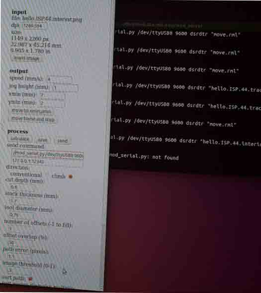
The size in the right corner listed is the size of the image 22.987 x 45.214 mm.
The output format is the Roland MDX.20
The process is - PCB Traces(1/64)
speed 4 - how fast is the machine cutting.
jog height 1mm - how far up above the board does the machine go when it needs to move.
xmin - 20 mm
ymin - 20 mm
x and y location seen from the lower left corner - start of the image.
We click on - move to xmin,ymin.
Only works in absolute mode from the lower left corner.
Program that is running as a server on that computer - mod_serial.py/dev/….
cut depth - 0.1mm
tool diameter - 0.4mm
number of offsets - 4 (we don´t remove all the kopar since it´s not needed and it ruins the tool) we tell it to go around 4 times if it can fit.
offset overlap 50% - means it cuts ones and then it moves away half of the tool diameter.
path error 1.1 pixels - calculation assist - if you allow for a small error it will actually move in a straight line instead of like stair moves.
image threshold - .5 - which value will be cut - anything below .5 anything darker then 50% gray is going to be cut - above that not cut.
sort path - 1.5 limits the amount of movements it has to make.
Bas sets up the server.
Computer is set up.
Now We set up the cutter. We start by putting our finger under the mini bit - loosen it and then slide it all the way up and tighten it but not too hard.We make sure that the machine is on and then we click on view and the machine moves to the zero point. Press view again if we want to the machine to stop that if the machine is doing something we don´t want it to do. In order to reset we press the up and down button at the same time. Now we press the down button in order to bring the tool down and set it the way we want it. I can bring it all the way down since we did slide the tool all the way up before. It´s safe and then I bring it up a little bit. Then I hold the mini bit while I loosen it so it will not fall down then I lower it down so it sits on the surface. Then we turn it a little bit clockwise or tap it so anything that might be on the tip is moved away. Then I hold the bit with my finger and tighten it with only two fingers - not too tight. Then we go to the computer and I change the xmin to 5 and the ymin to 2 and I click on move to xmin,ymin.
Always hit calculate and then we hit send.
When it´s finished we put in the other mini bit in 1/32 in order to cut the outlines. Then we open the other file that we downloaded - interior png and then we do the same thing as before we choose the output format and the process PCB outline. We click calculate and then send. We can right click and we can rotate the image to see. Nothing happened when we hit send - it said mod_serial not found we have to put ./ in front of the mod_serial…. this is a trick. Then hit send again.
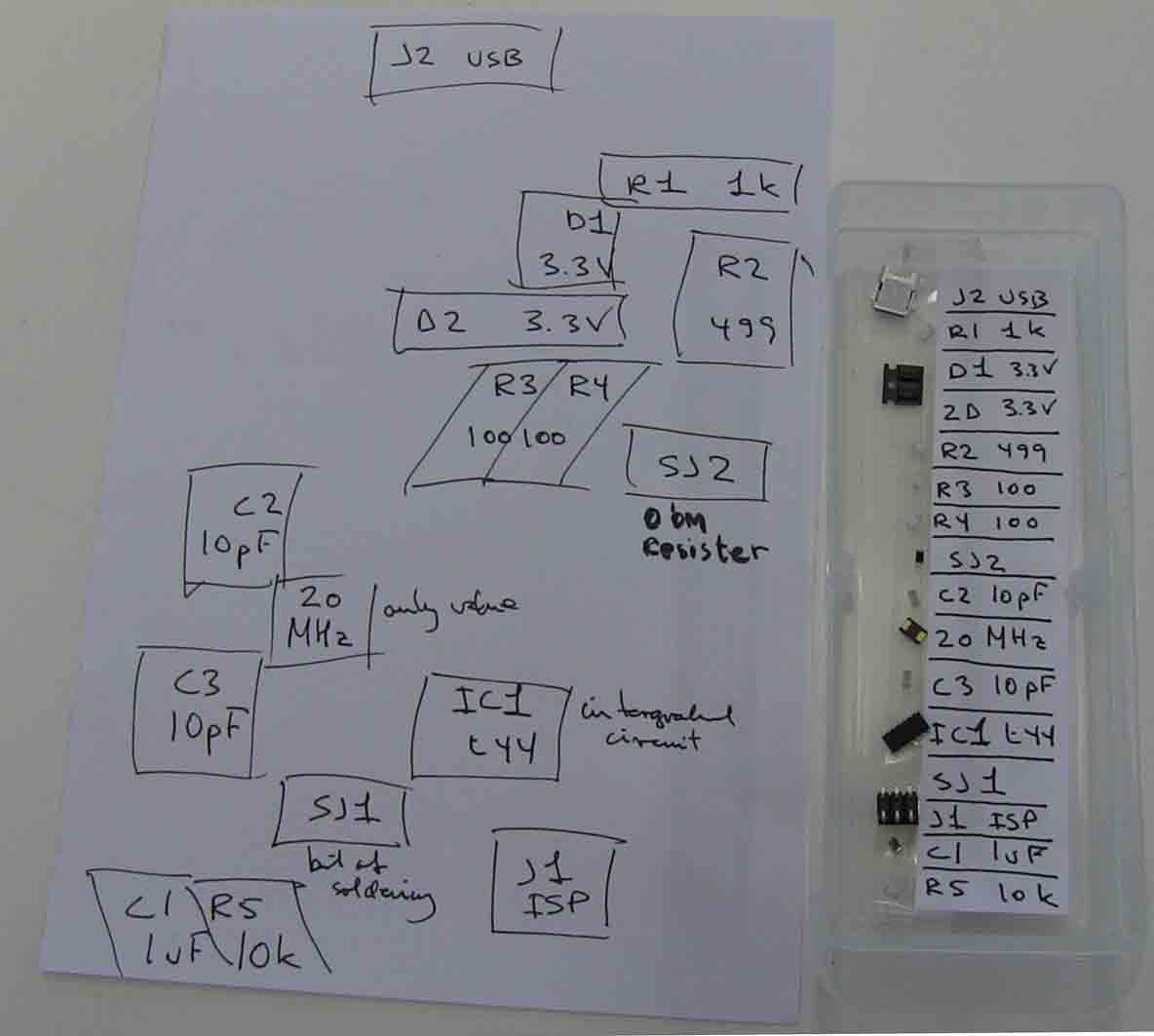
Now I go in the computer and I find the image for the board with all the parts that I need. I draw it up and write it up. All the pieces are so small and they are not marked. We write them down on a piece of paper and then put a strip of clear tape so we can put the pieces next to their name.
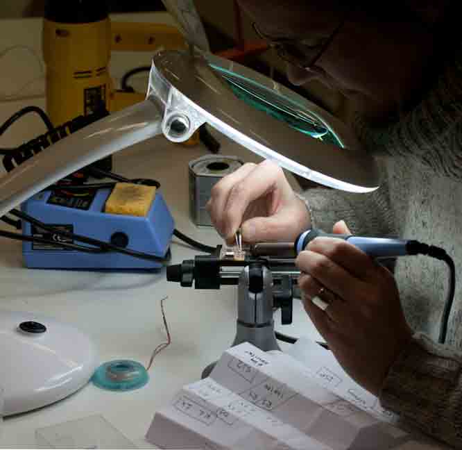
The next step is soldering the pieces on the board. I started by putting the USB piece first on. Then I noticed that it wasn´t quite in the right place so I had to use the heat gun in order to get it off. Everything went smooth after that but I was lucky to have a magnifying glass with a good light.
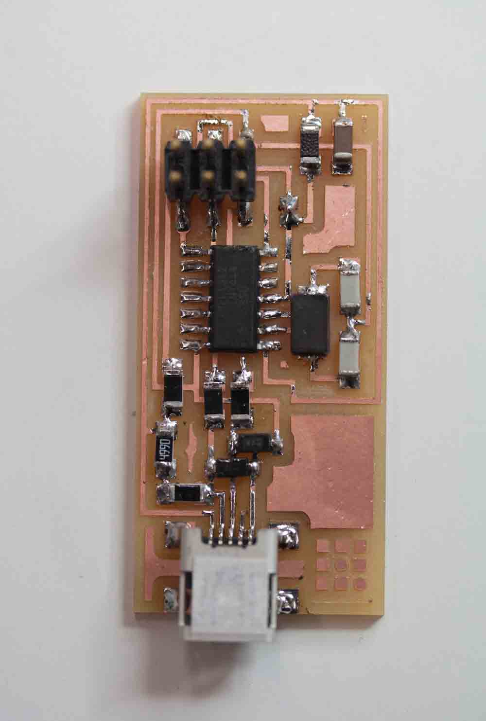
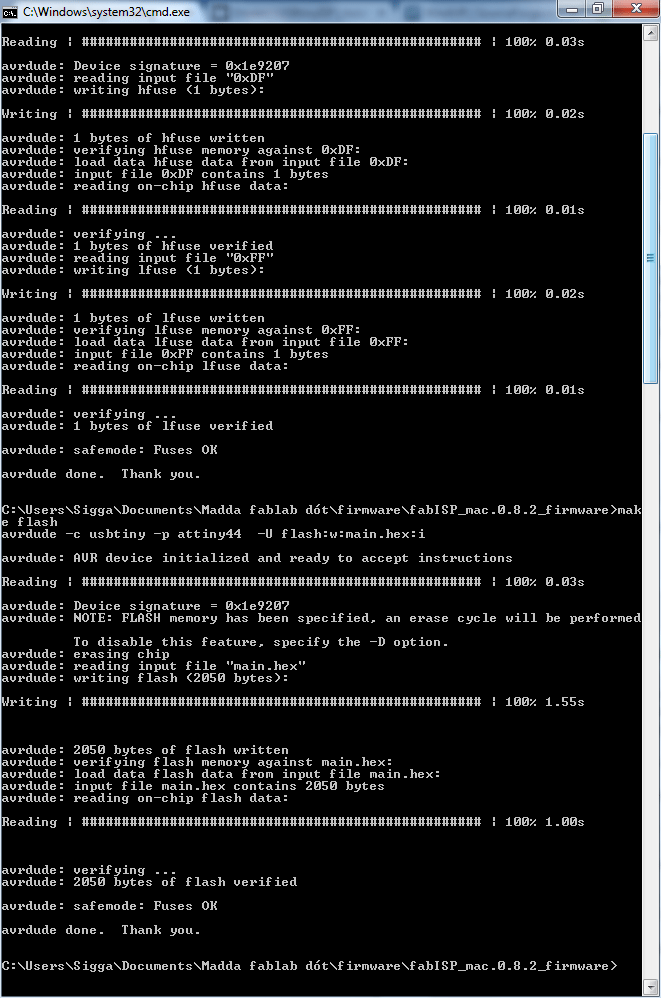
I checked the board with the machinge ground to ground and V to V and I got a nice peep everytime which means that everything was the way it´s supposed to be. The next step was to program the board. I followed these instructions:
http://fabacademy.org/archives/2015/doc/programming_FabISP.html
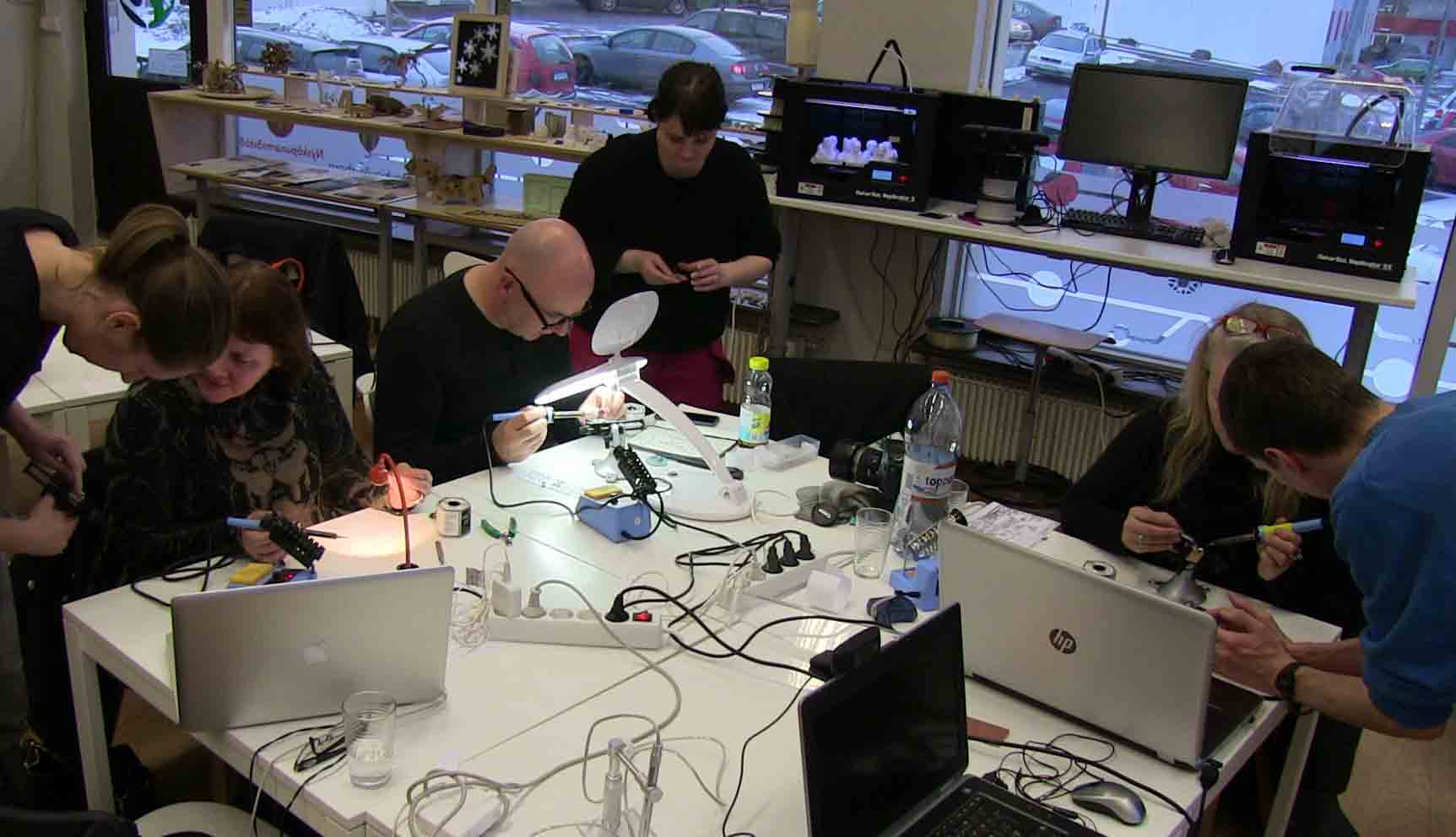
and everything went well. We all helped each other out during this so it was a bit of a group effort.
Lecture from Neil
PCB fabrication
etching
lithography, transfer
ferric/cupric chloride, ammonium/sodium persulfate
MSDS safe materials
waste disposal
machining
tools
0.010
1/64
1/32
fixturing
orientation
zeroing Don´t tighten the screw too much - begnners m
lifetime rough edges mean that the tool is at it´s end. Lifetime in the tens
deburring
cleaning
cutting
printing
plating
sewing
PCB materials
rigid
FR4 (epoxy glass)
FR1 (phenolic paper )this is what we use.- essential to use FR1
flex
Kapton industrially used
#1 epoxy film, #1126 copper tape this is what we use.
high-frequency
teflon
glass
copper
0.5 oz: 17.5 um
1.0 oz: 35 um
2.0 oz: 70 um
board houses
AP Circuits, Advanced, Sierra, Screaming Circuits, Gold Phoenix. They all do the same thing
Bas added EuroCircuits. OSH Park
design rules
width/spacing (15, 5 mils)15 thousands of an inch
layers different layer boards - 1.5 layer board is a one laayer board with a few crossovers. Fun to use as few layers as possible.
1, 1.5, 2, 4, N
solder mask, silk screen
vias
blind, buried
components Octopart
through-hole
surface-mount
chip-scale much higher feature size - much harder to solder(utective)
breadboards
assembly
solder
eutectic
flux
wire, paste, bar - paste has a lifetime and need to be refrigerated. - really using if soldering a lot.
manual, reflow, wave
ROHS
stuffing
component orientation
tacking down parts
bottom to top, inside to outside
washing
desoldering koperbraid
braid
hot air hot air gun - to get rid of parts that we don´t want. Hold the piece that we don´t want with tweezers and then heat the part that we don´t want until it falls off.
gravity
cutting traces, adding jumpers
pick-and-place
encapsulation protecting your board from the enviroment. Built somethng around it.
CAM
fab modules
linewidth
NOTES
Stuffing the board - bottom to the top and inside to out. frst I bring in the iron - hold the piece down with small tweezers - using the solder to hold the pack down.
Careful with fumes. Washing the parts?
A lot ef editing can be done with a knife afterwards in order to fix mistakes.
What are the parts and how do you orient them. - this week
David Andy Valentin
hello.ISP.44.cad board components traces interior
hello.ISP.44.res.cad board traces interior
inventory microcontroller crystal USB connector ribbon connector Zener diode jumper
firmware.zip
USB power
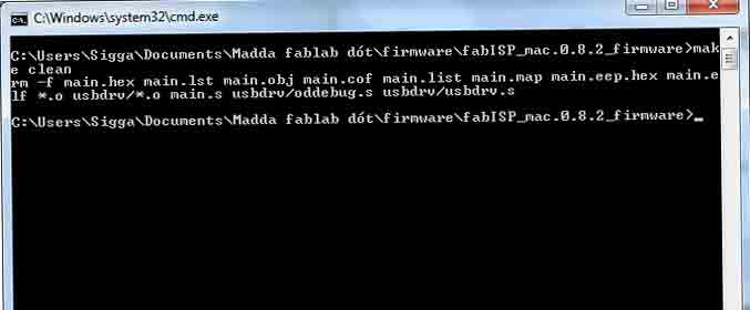
make clean
make hex
(sudo) make fuse (check programmer in Makefile, may need to repeat)
(sudo) make program
desolder SJ1 and SJ2
make IDC ISP cable, connecting header pin 1 to pin 1, check wires
Ribbon cable push it down - take it out and let it relax and put it in again and press it the second time.
How to mill the board and stuff the board this week and if there is time program it to see if it works.
watch tutorials from the website 2014 or 2013.
http://academy.cba.mit.edu/classes/embedded_programming/hello.ISP.44.components.png
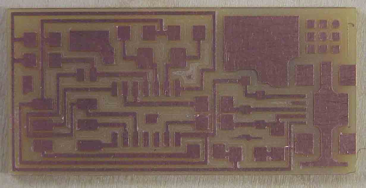
This is the board we are going to make
.